3D MORI · 3D Movement Oriented Relapse Index Version 1.0
Relapse happens in three dimensions.
The index we judge it by does not.
3DMori — the 3D Movement Oriented
Relapse Index — measures the movement of every
tooth as a rigid body in six degrees of freedom, recovered automatically from the crown
surface itself. It is fully automated and operator-independent: no
calipers, no hand-placed landmarks, no examiner judgement enters the number.
A three-dimensional relapse index invented and automated by A. A. Nazan.
70–90%of finished cases show measurable relapse in long-term follow-up
6 of 28teeth that Little’s irregularity index looks at
1plane it measures in — the other two are discarded
6 DOFper tooth, per visit, measured automatically by 3DMori
Origin
The case that started it
3DMori did not begin as a product. It began with one relapsed case — a finished,
well-retained smile that had quietly moved — and two instruments that could not agree on
whether anything had happened at all.
2.5 mmmeasured in three dimensions on 3Shape OrthoAnalyzer
1 mmscored by Little’s Index — and filed as “clinically insignificant”
Where does that “insignificant” line sit? It traces to a 1975 survey at the
University of Washington in Seattle, drawn up when a fixed appliance was the only way to
finish a case. Put the same survey to today’s clear-aligner patients and
neither the threshold nor the classification would survive. It writes off, as noise, the
smile that millions of people have invested their money, their effort and their years into.
And the notion that a clinician’s responsibility for a result ends
one year after debond belongs to the same lost world. Both are
stone-age orthodontics — rules from an era that no longer exists, still used to judge
the one that does. 3DMori exists to retire them.
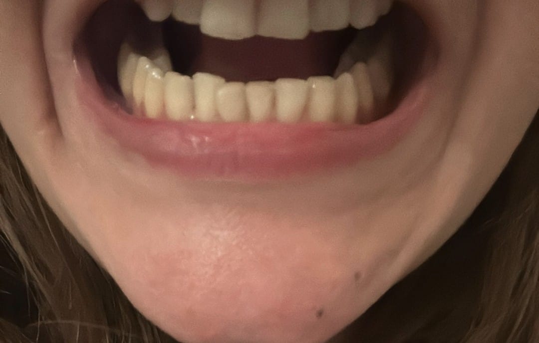
Add the case photo at website/assets/origin-case.jpg
A finished lower arch, one year on. Measured in three dimensions it had moved 2.5 mm; the fifty-year-old index recorded 1 mm and called the case stable.
I Why 3DMori was born
A failure everyone sees, that no instrument records, and no one owns.
Ask any orthodontist what happens after the appliances come off and the answer is the same
everywhere: the teeth move back. Not all of them, not all the way, but the great majority of
finished cases give up part of the alignment they were handed. The most-cited long-term
follow-ups place the proportion of patients with clinically detectable post-treatment relapse
at between seven and nine in ten, and the drift does not stop when retention
ends — it continues for decades.
Now ask who is responsible for it, and the answer evaporates. Four defences are given, and
every one of them is accepted:
The clinician
Responsibility ended at debond, where the result was — by every record in the file, including the final index score — excellent. Nothing afterwards is attributed to how the case was finished.
The patient
Told it is a compliance problem: the retainer was not worn enough. No measurement in routine practice can confirm or refute this, so the explanation cannot be tested and is never withdrawn.
The appliance maker
Points to the trials, which show their retainer performs no worse than the alternatives. The trials are real. What they measured is the question.
The evidence base
Systematic reviews of retention conclude, again and again, that there is insufficient evidence to prefer one protocol over another — and so no protocol can be held to account.
Every one of those defences rests on the same instrument. In the literature and in the clinic,
relapse means, almost always, one number: Little’s Irregularity Index.
And that number is a sum of five distances measured in a single flat projection of the lower
front six teeth. If a failure is not a contact-point displacement in that one plane, the index
does not merely under-report it. It returns zero.
That is the gap 3DMori was born in. Not a gap in clinical skill, and not a gap in retainer
design — a gap in measurement. You cannot assign responsibility for a
failure your instrument cannot record, compare two treatments along an axis it does not have,
or improve an outcome you cannot resolve.
II The instrument
Little’s Irregularity Index, and the eight things it cannot see
Published in 1975, the index is the sum of the linear displacements of the five anatomic contact
points of the mandibular anterior six, measured in the occlusal projection. Its virtues explain
its survival: one number, one caliper, one cast, no radiation, near-universal adoption. Its
limitations are structural — they follow from the definition itself, so no
amount of care in applying it can remove them.
I
It is a projection — and a projection destroys an axis by design
Every measurement is taken after flattening the arch into the occlusal plane. That operation deletes one of the three spatial dimensions outright. Whatever component of a tooth’s movement pointed up or down is gone before the caliper touches the cast.
II
Blind to extrusion and intrusion
A tooth that erupts or intrudes moves along precisely the axis the projection discarded. An incisor can extrude two millimetres, deepen the overbite, take a case to visible occlusal trauma — and the index still reads what it read at debond.
III
Blind to torque
Torque loss rotates the tooth about its mesio-distal axis: the crown tips labially while the root goes the other way. The contact points can stay put in the projection throughout, yet this is the movement that decides whether the roots are still in bone. The index scores it at zero.
IV
Blind to pure rotation about the long axis
Rotate a crown about its own long axis and its contact points travel around a small circle; the distances between them can be preserved almost exactly. Rotational relapse is among the best-documented failures in orthodontics, and the one most often visible to the patient in the mirror.
V
Blind to bodily movement of a whole segment
If a group of teeth drifts together, every distance between them is unchanged. The index measures relationships inside the segment, never the position of the segment in the arch or of the arch in the face.
VI
Six teeth out of twenty-eight
The index covers the mandibular canine-to-canine segment and nothing else. Premolar rotation, molar uprighting, inter-canine and inter-molar width, the entire upper arch: all outside its scope.
VII
One scalar, with no attribution and no direction
Five distances collapse into a single figure. It cannot say which tooth moved, which way it went, or whether one tooth moved four millimetres or four teeth moved one. There is nothing in it a clinician can act on.
VIII
Its measurement error is the same size as the effect
A hand-held caliper, a human eye, a cast, and a judgement about where a contact point lies on a worn tooth. Inter-examiner differences sit on the same order as the changes being reported — the very operator dependence 3DMori removes.
The consequence, stated plainly
A Little’s score of zero is not a clean bill of health. It is the absence of one kind of failure, in one plane, in one sixth of the dentition. Used as an outcome measure it introduces a systematic bias towards the conclusion that nothing happened — and therefore that nothing needs to be explained, compared, improved, or answered for.
The same tooth, the same visit, two instruments. Extrusion, rotation and torque loss are the three commonest forms of post-retention change; none has a component in the plane Little’s index measures, so the sum of the five contact-point displacements is unchanged and the case is entered as stable. Values are illustrative, of the magnitude 3DMori resolves routinely.
What each instrument can resolve
Post-treatment change
Clinically significant
Little’s index
3DMori
Contact-point crowding, occlusal plane
Yes
measured
measured
Extrusion / intrusion (vertical)
Yes — overbite, occlusal trauma
invisible
mm, signed
Torque loss (labiolingual inclination)
Yes — root position, stability
invisible
degrees, signed
Rotation about the long axis
Yes — the patient sees it
near-invisible
degrees, signed
Mesio-distal tipping (angulation)
Yes — contact quality
partial, indirect
degrees, signed
Bodily drift of a whole segment
Yes — arch position
invisible
mm, 3 axes
Inter-canine & inter-molar width change
Yes — classic relapse route
out of scope
measured
Premolars, molars, the entire upper arch
Yes
out of scope
every segmented tooth
Which tooth moved, and in which direction
Essential to act on it
not reported
per tooth, per axis
Error bar on the individual figure
Essential to trust it
none
registration residual
III The evidence
Beyond Little’s Irregularity Index: retention belongs in three dimensions
Little’s Irregularity Index (1975) is fundamentally a measure of anterior contact-point
irregularity — not of three-dimensional tooth position, and not of whether the arch
geometry achieved at the end of treatment has been preserved. The problem is that this simple
index has since been used to compare the clinical effectiveness of very different retention
systems, which behave differently in three dimensions while returning similar index values.
Macauley et al. (2012) questioned its reliability and continued use in a
paper titled “Using Little’s Irregularity Index in orthodontics: outdated and
inaccurate?”, demonstrating limits in reproducibility.
Devine et al. (2022) emphasised similar limitations and proposed a more
comprehensive Orthodontic Alignment Index, noting the index is insensitive to several kinds of
three-dimensional change.
What Little’s index does not adequately describe includes:
Rotationabout the tooth’s long axis
Inclination & torquelabiolingual root position
Angulationmesio-distal tipping
Vertical changeextrusion and intrusion
Transverse changeinter-canine & arch width
Arch geometrylength, depth, symmetry
The clinical relevance shows most clearly in fixed-retainer studies.
Shim et al. (2022) compared CAD/CAM-bent stainless-steel retainers with
conventional stainless steel and the highly flexible Ortho-FlexTech system. Differences in
anterior irregularity were limited, yet substantially greater loss of inter-canine width was
seen with Ortho-FlexTech — the CAD/CAM group kept roughly 1.23 mm
more inter-canine width at six months.
Çokakoğlu et al. (2024), over three years, found greater changes in
inter-canine width and arch length in dead-soft and connected-pad retainers, while CAD/CAM
NiTi and multistranded steel maintained mandibular stability better.
More recent three-dimensional work strengthens the argument.
Abbas et al. (2024) used serial STL superimposition and detected
significant tooth movement in multiple planes — including rotation — despite
limited change on conventional model measurements.
Most importantly, Köck et al. (2026) evaluated 226 dental arches with
tooth-specific three-dimensional coordinate systems: no significant
differences appeared between fixed-retainer types on Little’s index alone, but in three
dimensions they did — canine rotation and vertical translation were among the commonest
instabilities, and CAD/CAM and robotically-bent retainers showed lower magnitude and
variability than conventional Twistflex.
1975Littlethe irregularity index — anterior alignment as one number
2012Macauley“outdated and inaccurate?” — reproducibility questioned
2022Devinea broader alignment index; index insensitive to 3D change
2024AbbasSTL superimposition reveals movement indices miss
2026Köck226 arches; 3D differences where the index sees none
2026Nazan3DMori — a standardised, automated 3D relapse index
Are we truly measuring retention?
Geometric Preservation Capability
Definition — the ability of a retention system to preserve,
over time, the three-dimensional dental and arch geometry established at the
completion of orthodontic treatment. This shifts the assessment of retention from simple
irregularity toward preservation of the complete treatment result.
Orthodontics has described the ideal arch geometrically for over a century — the Bonwill triangle and the Hawley circle set arch form from the condyles and the incisor point. Retention is the task of preserving that geometry. 3DMori measures it directly: inter-canine and transverse width, arch length and depth, symmetry, and overall geometric distortion.
At the individual tooth level, 3DMori evaluates rotation, torque and
inclination, angulation, and three-dimensional translation. At the arch level
it adds inter-canine width, transverse width, arch length, arch depth, symmetry and overall
geometric distortion — every figure produced automatically, without operator input.
Similar Little’s Index values do not necessarily indicate equivalent stability.
Retention success should be reconsidered: not as the mere prevention of anterior crowding, but
as the preservation of the three-dimensional geometry achieved at the end of
orthodontic treatment.
IV The method
Stop measuring points. Measure the tooth — automatically.
The whole of 3DMori follows from one observation. Between two scans of the same patient a crown
is a rigid body: it cannot deform, only rotate and translate. A single rigid
transform describes the entirety of what that tooth did — and 3DMori recovers it without a
single hand-placed landmark or examiner decision.
It registers the crown surface at follow-up onto the same surface at
baseline. Tens of thousands of vertices take part, and averaging over them drives detection
noise down; a handful of hand-placed landmarks would propagate it instead. Crucially,
no landmark detection on the follow-up scan enters the result at all.
Automated end to end — and operator-independent
Segmentation is performed by deep learning; registration and the six-component
decomposition are deterministic geometry. From two STL files to six numbers per tooth, no step
asks a human to place a point, choose a plane, or read a caliper. The same scans give the same
result on any machine, on any day — the operator variability that dominates
Little’s index is designed out, not merely reduced.
The segmentation model was trained on 5,000 dental models; the geometry that follows is deterministic and reproducible.
Version 1.0 — measure on clean scans, without brackets or wires
Because the model was trained on 5,000 clean STL dental scans, Version 1.0
expects models with no brackets and no bonded wire. When a fixed appliance is
present it interferes with automatic segmentation and with locating the facial axis and the
mesial and distal points, so the measurement should not be trusted. For now, measure on
appliance-free scans — pre-treatment, post-debond, or a retention check on a clean arch.
A training batch that reads bonded appliances directly is planned for release around
the new year, and it will be automated in the same hands-off way. Until then, in
unavoidable cases the brackets and wire can be digitally removed from the STL file and the
scan measured automatically.
TranslationTransverseMillimetres. Positive toward the patient’s right.
RotationTorqueDegrees. Positive when the crown leans buccally.
RotationAngulationDegrees. Positive when the occlusal end leans mesially.
RotationRotationDegrees. Positive turning mesio-buccally about the long axis.
The pipeline
01 · INPUT
Intraoral scans or digitised casts
Upper and lower STL at baseline and at each follow-up. Up to four follow-ups, every one compared against the baseline — relapse is drift away from the treated result, so chaining would measure the drift of the drift.
02 · SEGMENT
Every crown identified and labelled — by deep learning
A deep-learning model splits the arch into individual teeth with FDI labels and extracts a point cloud per crown, with no manual tooth-picking. Each scan is segmented once and reused across every comparison it takes part in.
03 · DATUM
The superimposition datum is chosen, then tested
The palate cannot be dragged by relapse — but it must be present in the scan. 3DMori detects a palatal vault, measures whether it can hold a rigid pose, and falls back to a trimmed consensus over the dentition when it cannot. Which datum was used, and its error, is reported with every result.
04 · REGISTER
Follow-up superimposed on baseline, crown by crown
Registration uses only the coronal 70% of the crown — not a tuning constant but the fix for the largest error the pipeline can make. See validation.
05 · RESOLVE
One rigid transform per tooth, split into six components
Displacement of the crown centroid in three axes, rotation in three, plus the registration residual registration_rms_mm that bounds how far each figure can be trusted.
06 · REPORT
Per tooth, per arch, and over time
Severity per tooth, the worst tooth by displacement, an arch roll-up, and the anterior six broken out so the result can be set beside a conventional Little’s score — because where the two disagree is the entire argument.
V Validation
What was measured, and what was not
A new index is only worth the errors it can rule out. 79 automated checks run against real crown
geometry with known transforms applied, so every reported figure can be compared against the
answer it should have produced — the same suite runs on every change, so the method cannot
quietly drift.
Synthetic follow-up, applied to a real scan
Worst false displacement
Worst false rotation
Rigidly repositioned copy
0.000 mm
0.00°
Plus 25 µm scanner noise, a third of vertices dropped
0.003 mm
0.03°
Plus gingival margin cut 15% further up the crown
0.000 mm
0.00°
One tooth moved 1.200 mm
reports 1.200 mm; neighbours 0.000 mm
—
The error budget — and why the algorithm is not the limit
A reporting threshold is not a precision figure. It is the sum of everything that can move a
number when the tooth did not, and the honest way to publish one is to show the terms.
Independent errors add in quadrature, and that settles which instrument is limiting:
√(0.10² + 0.003²) = 0.100 mm.
The algorithm term disappears. 3DMori is roughly thirty times more precise
than the scanner feeding it — the threshold is a statement about hardware,
not the method, and will fall on its own as intraoral scanners improve.
The degree does not fall with the millimetres. Rotation is recovered from the whole crown
surface, so an angular error is a surface error divided by the crown’s lever arm:
0.05–0.10 mm across a 4–5 mm radius is
0.6–1.4°. One degree sits in the middle of that band.
VI Who it is for
Three questions that could not be asked before
Clinics
At every recall: which teeth moved, how far, in which direction, and is it beyond the measurement error. A retention decision made on six numbers per tooth — and a record that can answer the patient’s question three years later.
Researchers
An outcome measure with components, attribution and a per-tooth error bar — so a retention trial can report where two appliances differ instead of returning another null. Automated, so it is reproducible across sites and operators.
Appliance developers
Vertical, torque and rotational control measured separately, on real patients, against a fixed baseline. A retainer that is genuinely better along one axis can finally demonstrate it.
❦
Get started
Bring your baseline and your recall scans. Get the six numbers per tooth — automatically.
The 3DMori portal keeps your patients, their scan timeline and every analysis in one place.
Upload an upper and a lower STL for the baseline, add each follow-up as it comes in, and the
comparison runs against T0 every time — with no operator input.